
Inclinometer Installation and Applications: Complete Technical Reference for Structural Monitoring
Structural tilt monitoring has become increasingly important as aging infrastructure demands continuous assessment of stability and movement. Inclinometer sensors provide precise measurements of angular changes in structures ranging from bridge piers and settlement to building foundations, offering engineers actionable data for maintenance planning and safety assessments.
This technical reference examines practical aspects of inclinometer installation, explores diverse applications across infrastructure sectors, and addresses accuracy requirements for various monitoring scenarios. Whether you’re implementing tilt monitoring for the first time or optimizing existing systems, understanding these fundamentals improves measurement reliability and project outcomes.
Understanding Inclinometer Technology
What is an Inclinometer?
An inclinometer measures the angle of tilt or inclination relative to gravity’s direction. In structural monitoring, these sensors detect angular changes indicating settlement, deformation, or movement in infrastructure components. Modern digital inclinometers utilize MEMS (Micro-Electro-Mechanical Systems) technology, providing high-resolution measurements in compact, robust packages suitable for long-term field deployment.
Basic Operating Principle:
Inclinometers contain accelerometer elements that measure the components of gravity along different axes. By analyzing these gravitational components, the device calculates tilt angles with precision reaching up to 0.0003 degrees in high-resolution models. This level of sensitivity enables the detection of minute structural movements long before they become visible to inspectors.
Types of Inclinometers for Structural Monitoring
Single-Axis Inclinometers: Measure tilt in one direction, suitable for monitoring known movement vectors such as retaining wall rotation or pier settlement along a specific axis.
Dual-Axis Inclinometers: Provide two-dimensional tilt measurement, capturing angular changes in both longitudinal and transverse directions. These sensors offer complete surface tilt monitoring, ideal for applications where movement direction may vary or isn’t predetermined.
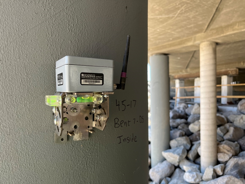
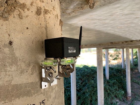
Wireless Inclinometers: Combine tilt sensing with wireless communication, enabling remote monitoring without cable installation. These systems operate maintenance-free for extended periods, making them practical for difficult-access locations or large-scale monitoring networks.
How to Use Inclinometer Sensors: Step-by-Step Implementation
Planning Phase
- Define Monitoring Objectives: Before sensor deployment, establish clear objectives for your tilt monitoring program. Are you tracking foundation settlement? Monitoring pier deflection under traffic loads? Assessing retaining wall stability? Different objectives influence sensor selection, placement density, and measurement frequency requirements.
- Determine Required Accuracy: Inclinometer accuracy requirements vary by application. Foundation settlement monitoring may require a resolution of approximately 0.001 degrees, while bridge bearing assessments typically demand lower precision, on the order of 0.01 degrees. Sensor specifications should be selected to match the measurement requirements while also considering budget constraints.
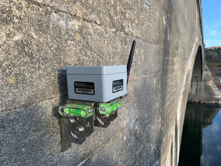
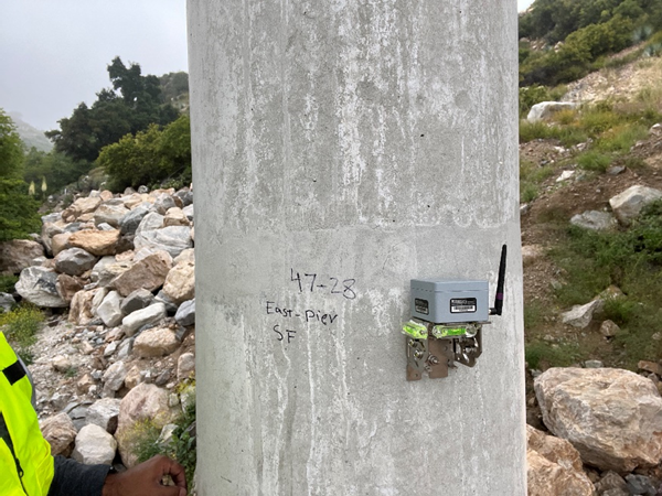
- Identify Optimal Sensor Locations: Select mounting positions that represent structural behaviour you want to monitor. For bridge piers, mount sensors at heights corresponding to maximum deflection points. On retaining walls, place sensors at mid-height and near the top where rotation is most pronounced. Consider accessibility for installation while maintaining measurement relevance.
Surface Preparation for Inclinometer Installation
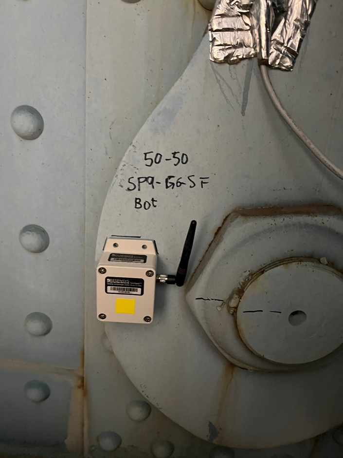
- Steel Structures: Clean mounting surfaces thoroughly using degreasing solvents to remove oils, dirt, and loose paint. Surface preparation directly impacts long-term sensor adhesion and measurement stability. Rough surfaces may require light sanding to create uniform contact between sensor base and structure.
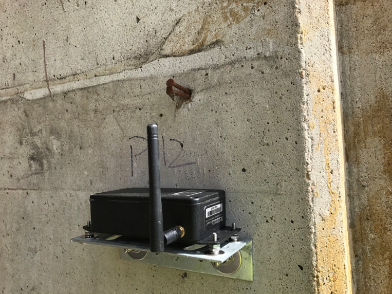
- Concrete Structures: Concrete presents unique challenges due to surface porosity and potential unevenness. Grind mounting areas smooth using diamond grinding pads, removing any loose material or surface contaminants. For severely uneven surfaces, apply quick-setting patching compound to create level mounting pads. Allow complete curing before sensor installation.
- Wood and Composite Materials: Natural materials like timber require additional consideration due to moisture content variations and potential surface deterioration. Create solid mounting points using marine-grade adhesives or mechanical fasteners. Account for material expansion and contraction in your installation design.
Physical Installation Process
Adhesive Mounting Method:
Self-adhesive mounting offers quick installation without structural drilling, particularly valuable for steel and sealed concrete surfaces.
- Temperature Verification: Conduct installations within manufacturer-specified temperature ranges (typically 10-35°C) for optimal adhesive performance.
- Surface Application: Apply mounting adhesive evenly across the sensor base, avoiding air pockets that could compromise bond strength or introduce measurement errors.
- Positioning Accuracy: Use a precision level to orient sensors correctly. Even slight misalignment affects baseline readings and complicates data interpretation. Mark reference points on the structure for future sensor replacement or verification.
- Curing Period: Allow adhesives to cure fully before activating wireless transmission. Premature movement can compromise bond integrity and introduce initial measurement errors.
Mechanical Mounting (Flange Installation):
For permanent installations or applications requiring maximum stability, mechanical mounting using anchor bolts provides superior long-term reliability.
- Drill Pattern Layout: Mark bolt hole locations precisely using the sensor mounting template. Verify alignment using a precision level before drilling.
- Hole Preparation: Drill anchor holes to specified depths, cleaning thoroughly to remove concrete dust that could prevent proper anchor seating.
- Anchor Installation: Install expansion anchors or epoxy anchors according to given specifications, verifying torque values to prevent over-tightening.
- Sensor Mounting: Position the sensor on mounting bolts, using alignment guides to maintain proper orientation. Tighten fasteners evenly to prevent unequal stress distribution.
- Sealing: Apply weatherproof sealant around the mounting perimeter to prevent moisture intrusion that could affect sensor performance or structural corrosion.
Wireless Network Configuration
- Gateway Placement: Position wireless gateways within reliable communication range of all sensors, accounting for potential signal obstruction from structural elements. Typical wireless inclinometers can communicate effectively with gateways over distances of up to 400 meters in the absence of significant obstacles.
- Initial Baseline Establishment: After installation, allow 24-48 hours for thermal stabilization before establishing baseline measurements. Temperature changes cause temporary tilt readings unrelated to structural movement. Record initial measurements under stable environmental conditions as reference points for future change detection.
Inclinometer Applications Across Infrastructure
Bridge Monitoring
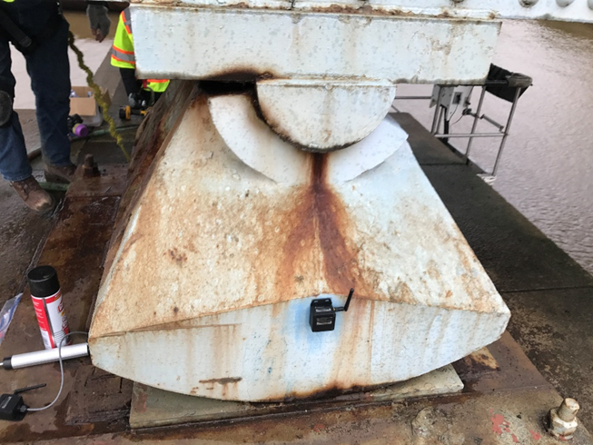
Pier and Abutment Settlement:
Foundation settlement represents one of the most common bridge structural issues. Inclinometer sensors mounted on piers detect angular changes indicating differential settlement, often appearing years before visible damage occurs.
Installation typically involves sensors at pier tops and mid-height positions, creating a profile of movement that helps engineers determine whether settlement originates from foundation issues or superstructure problems. Measurement accuracy of 0.001-0.003 degrees proves sufficient for most bridge pier monitoring, providing early warning months before settlement becomes visible during inspections.
Bearings allow controlled structural movement while supporting loads. Inclinometers positioned adjacent to bearings track rotation and tilting that might indicate bearing degradation or improper load distribution. This application requires lower accuracy (0.01 degrees) due to the relatively small angular changes associated with bearing issues.
Building Structural Health Assessment
Foundation Monitoring:
Building foundations experience settlement, particularly in areas with expansive soils or high groundwater tables. Inclinometers installed on foundation walls or structural columns detect angular changes indicating differential settlement patterns.
Early detection allows proactive stabilization measures before settlement causes structural damage or serviceability issues. Typical monitoring accuracy of 0.01 degrees suffices for foundation applications, as settlement-induced tilting generally exceeds this threshold by the time intervention becomes necessary.
High-Rise Building Sway:
Tall buildings experience wind-induced movement and thermal effects causing measurable tilt. Inclinometers positioned at multiple building levels characterize sway patterns and verify that movements remain within design parameters. This application often requires continuous or high-frequency measurement to capture dynamic responses during wind events.
During adjacent construction activities, inclinometers track existing structure movement potentially caused by excavation, dewatering, or vibration from construction equipment. Real-time monitoring enables immediate response to excessive movement, protecting both the existing structure and construction personnel.
Geotechnical Applications
Retaining Wall Stability:
Retaining walls restrain soil masses that exert lateral pressure potentially causing rotation or tilting. Inclinometers mounted at various heights along retaining walls detect rotation indicating wall movement or foundation issues.
Measurement accuracy requirements depend on wall height and retained soil characteristics, typically ranging from 0.003-0.01 degrees. More precise monitoring applies to walls retaining high-value infrastructure or those with marginal stability factors.
Slope instability threatens infrastructure built on or near hillsides. Inclinometer arrays across potential slide areas detect ground movement indicating developing landslides. Unlike traditional in-place inclinometers requiring periodic manual readings, wireless surface-mounted inclinometers provide continuous monitoring with immediate alerting when movement exceeds predetermined thresholds.
Excavation Support and Mine Monitoring:
Deep excavations require temporary support systems whose performance directly affects adjacent structure safety. Inclinometers on support walls track movement potentially indicating inadequate support or unexpected soil pressures. Continuous wireless monitoring during excavation enables rapid response to developing issues.
Dam and Water Infrastructure
Dam Embankment Settlement:
Earth dams settle and deform over time due to consolidation and loading changes. Inclinometers positioned along embankment crests and slopes measure angular changes indicating settlement patterns or potential instability. This application typically requires modest accuracy (0.01 degrees) but benefits from long-term measurement stability.
Spillway and Gate Structure Monitoring:
Concrete dam structures experience foundation settlement and thermal movements. Inclinometers track angular changes in spillway piers, gate frames, and other structures where excessive tilt could impair operational functionality or structural integrity.
Industrial and Energy Infrastructure
Wind Turbine Tower Monitoring:
Wind turbine foundations experience cyclic loading from rotor operation and environmental forces. Tower inclination monitoring detects foundation settlement or structural issues requiring maintenance. The harsh environment and difficult access make wireless inclinometers particularly valuable for wind energy applications.
Large storage tanks settle unevenly due to foundation conditions and operational loads. Inclinometers mounted around tank perimeters detect differential settlement that could compromise structural integrity or create operational issues with piping connections.
Crane and Heavy Equipment Foundations:
Industrial crane foundations must remain stable to maintain safe operations. Inclinometer monitoring detects settlement or movement potentially affecting crane rail alignment or foundation stability.
Inclinometer Accuracy: Understanding Specifications and Requirements
Resolution vs. Accuracy
Resolution defines the smallest angular change a sensor can detect and report. An inclinometer with 0.001-degree resolution can measure changes as small as one-thousandth of a degree.
Accuracy describes how closely measurements correspond to true tilt values. A sensor might resolve 0.001 degrees but have ±0.003-degree accuracy, meaning individual readings may vary by up to 0.003 degrees from actual tilt.
Understanding this distinction prevents over-specifying monitoring systems or expecting unrealistic measurement precision from sensors with inadequate accuracy specifications.
Factors Affecting Measurement Accuracy
Temperature Effects:
Temperature changes cause tilt readings unrelated to structural movement through two mechanisms:
- Thermal Expansion: Structures expand and contract with temperature variations, creating angular changes that may not indicate structural issues. Advanced inclinometers include temperature sensors enabling compensation for thermal effects.
- Sensor Drift: Internal sensor components experience temperature-dependent behavior. Quality inclinometers include temperature compensation algorithms minimizing drift over operating temperature ranges typically spanning -40°C to +65°C.
Installation Quality:
Improper mounting introduces measurement errors that persist throughout monitoring programs. Ensure mounting surfaces are level, clean, and structurally sound. Poor adhesion can allow sensor movement independent of structural behavior, creating false indications of tilt changes.
Vibration and Dynamic Loading:
Inclinometers respond to vibration and dynamic forces, potentially masking slower structural movements of primary interest. Digital filtering and appropriate measurement timing help separate dynamic effects from permanent tilt changes.
Long-Term Stability:
Sensor drift over months or years can obscure gradual structural movements. Select inclinometers with documented long-term stability specifications matching your monitoring program duration. Annual verification against reference measurements helps quantify and correct for any drift.
Accuracy Requirements by Application
| Application | Recommended Accuracy | Typical Measurement Range |
| Bridge Pier Settlement | 0.001-0.003° | ±5° |
| Building Foundation | 0.01° | ±10° |
| Retaining Wall Rotation | 0.003-0.01° | ±15° |
| Bridge Bearing Assessment | 0.01° | ±2° |
| Landslide Warning | 0.01-0.05° | ±30° |
| Dam Embankment | 0.01° | ±10° |
| Construction Monitoring | 0.01° | ±15° |
These recommendations provide starting points for system specification. Specific project requirements may demand tighter tolerances based on structural sensitivity, safety factors, or regulatory requirements.
Data Analysis and Interpretation
Establishing Baseline Measurements
Initial inclinometer readings establish baselines against which future measurements are compared. Collect baseline data over several days or weeks to account for:
- Daily temperature cycles causing thermal movement
- Traffic or operational loading patterns
- Seasonal environmental effects
- Initial sensor settling after installation
Adequate baseline periods improve ability to distinguish actual structural changes from normal operational variations.
Identifying True Structural Movement
- Temperature Correlation Analysis: Plot tilt measurements against temperature readings to identify thermal effects. Structural tilt that correlates strongly with temperature likely represents thermal expansion rather than permanent structural change. True settlement or deterioration appears as tilt changes independent of temperature patterns.
- Rate of Change Assessment: Sudden tilt changes often indicate measurement anomalies or installation issues rather than actual structural movement. Gradual, consistent changes over days or weeks more likely represent genuine structural behavior requiring investigation.
- Multi-Sensor Correlation: Compare readings from multiple inclinometers on the same structure or adjacent elements. Coordinated changes across sensors suggest actual structural movement.
Alert Threshold Configuration
Establish measurement thresholds triggering alerts or investigations:
- Warning Levels: Moderate tilt changes exceeding typical measurement noise but not indicating immediate concerns. These trigger increased monitoring frequency and engineering review.
- Action Levels: Significant tilt changes requiring immediate investigation and potential response actions such as load restrictions or structural shoring.
- Emergency Levels: Extreme tilt changes indicating imminent structural failure requiring immediate evacuation or closure procedures.
Threshold values depend on structure type, loading conditions, and consequences of failure. Conservative thresholds for safety-sensitive applications accept higher false alarm rates to prevent missed detections of genuine structural issues.
Advantages of Resensys Wireless Monitoring systems
- Wireless SenSpot™ Sensor: No wiring, minimal lane closure for installation
- Sensors with 10+ Years Battery Life: No need for battery replacement, maintenance or calibration in the field
- Easy Installation: Self-adhesive (e.g., steel) or Flange-mount (e.g., concrete)
- Quick Testing: Can be installed for short-term testing, easy to remove and reuse on other structures/pipelines and applications
- Long-term Monitoring: Designed to be used for long-term monitoring (e.g., several years)
- Small Size and Lightweight
- Being Suitable for Different Kind of Materials: Can be used on steel, concrete, timber, and composites
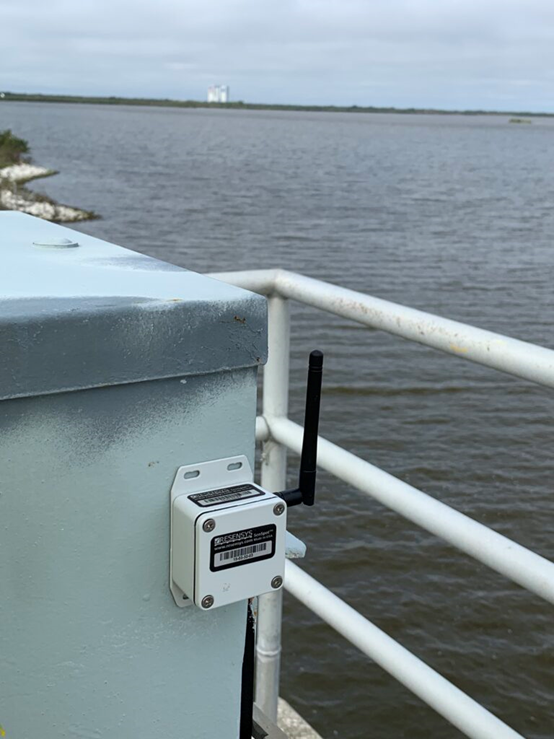
- Rugged, Weather Proof and Corrosion Resistant: Can operate in rain, snow, ice, high humidity, salty environment and extreme weather (-40°C to +65°C or -40°F to +150°F)
- Infrastructure Less: Battery Operated, Energy self-sufficient, No need for communication infrastructure at the pipelines
- Provide Data Visualization, Data Analysis and capability with AI/ML algorithms
- Provide Alert Services: Alert generation and management with customizable alert levels, automated structural diagnostics, capability of providing e-mail or text message alerts
- Very High-Resolution sensors
- Compatible with 3rd party sensors
Conclusion
Successful inclinometer implementation requires careful attention to sensor selection, installation procedures, and data interpretation practices. By matching sensor accuracy specifications to application requirements, following proper installation protocols, and establishing appropriate data analysis procedures, engineers obtain reliable tilt measurements supporting informed infrastructure management decisions.
Wireless inclinometer technology has simplified deployment and reduced maintenance requirements, making continuous tilt monitoring practical for applications previously relying on periodic manual inspections. As infrastructure ages and monitoring demands increase, understanding these systems helps professionals implement effective structural health monitoring programs.
Ready to Implement Tilt Monitoring?
Selecting appropriate inclinometer technology for your infrastructure monitoring needs requires understanding application-specific requirements and long-term program objectives.
Discover maintenance-free wireless inclinometer solutions with 10-year battery life
Contact our team today to learn how wireless inclinometer technology can improve your structural assessment programs and provide the continuous monitoring necessary for proactive infrastructure management.
Schedule Engineering Consultation. Discuss your tilt monitoring requirements with our structural monitoring experts
Frequently Asked Questions
Q: What wireless range can I expect from inclinometer sensors?
A: Open-air communication ranges reach 1 kilometer for wireless inclinometer SenSpot™. Structural steel and reinforced concrete reduce effective range, typically to 100-300 meters depending on wall thickness and reinforcement density.
Q: How do I verify inclinometer accuracy after installation?
A: Compare sensor readings against precision level measurements or known reference angles. Annual verification checks against calibrated reference instruments help detect sensor drift requiring compensation or replacement.
Q: Can I move inclinometer sensors to new locations?
A: Self-adhesive mounted sensors can be relocated to new monitoring points, making them cost-effective for temporary monitoring or applications where monitoring locations change over time.
Related Documents:
About Author
Matt
-
 Pipeline Monitoring Sensors: Complete Guide to Leak Detection and Real-Time Monitoring Systems
Pipeline failures cost the oil and gas industry billions of dollars annually
-
 Resensys SenSpots Monitor East Capitol Bridge Across Anacostoia River (Washington D.C.)
Piers of highway bridges over rivers are vulnerable to hydraulic damage caused